Harmonic currents generated by power electronics based devices create serious power quality problems in facilities. Particularly 3 phase AC frequency converters used for engine control generate harmonic currents during operation due to rectifier layer available in its topological structure. In this study, examination was focused on how harmonics generated by a 3 phase AC frequency converter changes according to frequency converter structure and filtering type. Current harmonic distortion (THDI%) values are compared depending on different load and application types.
Harmonic distortion, harmonic sources, failures caused by harmonics and calculations are given in this article. Solution methods of harmonics generated by AC frequencyconverters are assessed. Advantages and disadvantages of solution methods are assessed.
Harmonic current and voltages are generated by loads containing semi-conductors connected to grid [1,2]. Harmonic distortion caused by harmonic currents’ exceeding certain limit values creates various problems in a facility.
Power electronics converters used in different electronic systems create distortion effect in the grid by directly injecting harmonic currents to the grid. Basic component (i1) and harmonic (ih) currents in the current (is) to be withdrawn by a power electronic converter from the grid can be indicated as below.
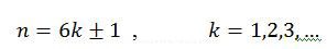
Theoretically, output current of the rectifier can be considered as clean DC current. Harmonic current frequencies of 6 pulse 3 phase rectifier and basic grid frequency are full times of n. [1,2].
Below given information is valid when the line inductance value can be negligible according to DC reactor inductance. Harmonic levels are calculated based on the below given formula:
RMS value of harmonic components is:
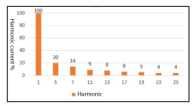
harmonic components are given in Image 1.
Image.1 6 Harmonic current content of theoretical square wave current of pulsed rectifier
Variation of wave shape created by adding harmonic currents to basic component current is indicated in Image 2. Only 5th Harmonic current was added to the basic component.
Image 2 Total current created by basic component and 5th harmonic component
Harmonic Sources and Effects on the Grid
Engine starters, frequency converters, computers and other electronic office equipments, electronic ballast lamps and LEDs, uninterrupted power sources, welding machineries and arc furnaces those are extensively used in industrial and commercial businesses and containing semi-conductors in its structure generate harmonic currents [2].
Harmonics cause overheating and bursts in transformers, engines, cables and other conductive assemblies and explosions and failures in power condensers. They also cause electronic card failures, faulty operations in switches and other protection equipments. Measurement and reading faults in sensitive equipments can be considered as failures caused by harmonics. It can also stated that harmonics cause losses due to the increase in RMS current.
If one or more of above given items are observed in the facility, harmonic sources at electrical substructure of the facility should be analyzed. Harmonics generated from harmonic sources in the facility shall not only negatively affect the facility but also the connected grid. This should be considered when a facility is being examined for harmonics.
In this study, basically harmonic effects of 3 phase 5 pulse frequency converters shall be examined.
Structure and Dimensioning of 3 Phase 6 Pulse Frequency Converter
Harmonic currents cause distortion in busbar voltage. If grid impedances and harmonic currents are known, theoretically voltage harmonics of any point on the grid can be calculated. The circuit diagram given in Image 3 indicates frequency converter fed from the grid and other components. ABB DriveSize software was used during frequency converter harmonic distortion calculations.
In following images, data used during modeling and harmonic distortion amounts created based on these data shall be given.
Image.3 Circuit diagram showing frequency converter and engine data. Technical data are indicated on the left hand column.
Image .4 Engine load data. Most important engine data required for harmonic calculation is the kW engine load data.
Image .5 Selected engine technical data.
Image .6 Inverter selection
Image .7 Inverter feeding unit data. Values are determined by the modeling program depending on inverter selection.
Image .8 Grid and transformer data.
Image .9 Calculated current and voltage harmonics
Modeling program performs Fourier analysis for frequency converter input current based on entered engine, transformer and inverter data and calculates amplitudes of harmonic currents [6]. Calculated harmonic currents are voltages induced by harmonic currents by passing over grid, transformer and inverter feeding unit impedances. Current harmonic distortion amount of the frequency converter selected for 100 kW engine having 6 pulse rectifier topology is found as 47,1% in the modeling.
Limit Values Related with Current Harmonics
Standard frequency converters used in industrial applications are generally not comply with current harmonic limits determined by IEEE519-2014 standard. Limit values of current harmonics mentioned in IEEE 19 standard are given in Table 1 [6].
Table .1 IEEE519 current harmonics limit values
ISC/IL rate given in this table means rate of the short circuit current at common connection point (PCC) of the grid against the facility load current.
Reduction of Harmonics Through Structural Changes to be Performed in AC Frequency Converter
Harmonics can be reduced by making structural changes in the frequency converter or performing an external filtration. Structural changes in the frequency converter can be source reinforcement, using 12 or more pulse structure, using controlled rectifier or increasing internal filtering within the converter [7].
Parameters having impact on harmonics in a frequency converter can be seen in Image .10. Frequency converter current harmonics depend on driver configuration and current harmonics depends on multiplying grid impedance with current harmonics.
Image .10 Factors affecting harmonics in driver
Table .2 Factors affecting harmonic distortion and their effects
Factor
Effect
Larger Engine
Higher current harmonic
Higher engine load
Higher current harmonic
Higher DC or AC inductance
Lower current harmonic
Higher pulse rectifier
Lower current harmonic
Larger transformer impedance
Lower voltage harmonic
Smaller transformer impedance
Lower voltage harmonic
Larger grid short circuit power
Lower current harmonic
Pulse Rectifier Usage
Rectifier connections having different pulse numbers are given in Image .11. Most used 3 phase AC frequency converter rectifier is 6 pulse model. This structure contains an inductance with DC condensers used for DC current regulation and 6 uncontrolled diodes. Coil may be at AC or DC side or completely be excluded. Despite 6 pulse rectifier is a simple and cheap solution, it generates 5th, 7th and 11th harmonics in high amounts particularly when used with low inductance coil [6,7].
Image .11 Input current harmonics based on different rectifier configurations
12 Pulse or 24 Pulse Diode Rectifier Usage
12 pulse rectifier is created by paralleling 2 pieces of 6 pulse rectifiers for feeding the common DC busbar. One double secondary transformer or 2 single secondary but different connection groups containing transformer is used for rectifier input. 300phase shift is available between transformer secondaries to feed both rectifiers. Benefit of this configuration is to eliminate various harmonics due to angle difference by grid feeding of transformers. Theoretically, smallest level harmonic to be seen at grid feeding side of double secondary transformer is 11.
Main disadvantage of this structure is the requirement of using high cost special transformer when compared with 6 pulse.
Principle scheme of 24 pulse rectifier is seen in figure y. In this structure there are 2 parallel double secondary transformers available with 150phase shift between them. Despite eliminating almost all low level harmonics, high cost is a serious disadvantage. Though, 24 pulse rectifier can be the cheapest solution for low harmonic distortion in very large strong frequency converter applications [3].
Phase controlled rectifier is created by replacing diodes available in 6 pulse diode rectifier with thyristors. Thanks to requiring a trigger for the thyristor to pass from cutting to transmission, the phase angle required for thyristor transmission can be adjusted. Delaying the ignition angle passes over 900 passes the DC busbar voltage to negative side. That allows flow of regenerative energy from DC busbar to grid.
Standard DC busbar and inverter configurations do not allow polarity replacement on DC busbar voltage. Instead, generally a second thyristor bridge is reverse-parallel connected to the first one and current polarity replacement is enabled. In this configuration, first bridge functions in rectification mode and second bridge functions in regeneration mode.
Phase controlled rectifiers also create commutation notches on the grid voltage. Notches particularly cause serious switching errors in systems with low grid short circuit power. Angular position of the notch is changed depending on driver’s switching angle.
In Image .12,
Rsc = Short Circuit Rate (Short circuit power at PCC point / facility total power)
Image .12 Distortion amounts in different rectifier types. Distortions are given as % based on RMS value. Values may vary depending on application.
IGBT Bridge Usage
There are many advantages of using self-controlled elements in the rectifier bridge topology instead of phase controlled or non-controlled power electronic elements. Similar to phase controlled rectifiers, regenerative operation is possible in IGBT rectifiers, and also DC busbar voltage and power factor can be adjusted independent from the load flow direction.
Current wave shape withdrawn from the grid in IGBT rectifiers is almost sinusoidal. Despite generating low level harmonics at a very low amount, it may generate high level harmonics at relatively high amounts in various situations. Reactive power can be generated with IGBT rectifier.
Basic disadvantage of IGBT rectifier is the high cost arising from the IGBT bridge.
DC or AC Coils With Higher Inductance
Connecting an adequately large coil at AC input or on DC busbar of frequency converter will considerable reduce harmonic distortion of the frequency converter. Image 13 indicates wave shape change in applications with and without coil.
Image .13 Impact of coil placement on the line current
Amount of the voltage harmonic depending on the current harmonic shall be changed based on grid short circuit rate (Rsc). Higher rate shall mean lower voltage distortion. Voltage harmonic distortion amounts to be created based on the grid circuit rate are seen in Image 14.
Image.14 THD Voltages based on driver type and transformer size
As inductance of the coil placed at AC or DC side on the driver increases, current harmonics at frequency converter input shall be reduced. When current harmonics are reduced, current harmonics induced by current harmonics shall similarly be reduced.
Other Methods for Reducing Harmonics
Filtering is the basic method implemented for reducing harmonic in industrial and commercial companies. Filtration methods are basically divided into two as active and passive filters.
Single Arm Tuned Passive Filters
Principle diagram for Single Arm Tuned passive filter is given in Image .15. Single arm tuned filters accorded to a low level harmonic frequency with distinct harmonic distortion in the system [5]. This harmonic arising from loads in industrial applications are generally 250 Hz and 350 Hz as 5th and 7th harmonic frequencies.
Image .15 Single arm tuned passive filter principle scheme
Tuned filters indicate higher success in applications whose grid equivalent impedance does not continuously change or relatively change as limited. Filter’s harmonic filtering performance is closely related with amount of condensers to be added in the system at grid frequency and self distortion amount of the grid. As various harmonic sourced loads are activated and deactivated at different times in low voltage applications, single arm tuned filter can be overloaded depending on the design. Filtration performance is higher in high voltage applications due to lower load and less variable grid impedance.
Multiple Arm Tuned Passive Filters
Principle diagram for multiple arm tuned passive filter is given in Image 16. Multiple arm tuned passive filters are accorded to low level more than one harmonic frequency with distinct harmonic distortion in the system [5] Filtration performance is higher than single arm tuned filter.
Image .16 Multiple arm tuned passive filter principle diagram
Multiple arm tuned passive filters are generally used in facilities with big and strong DC frequency converters. Activation of filters should be performed from the arm with lower frequency to the arm with higher frequency. Similarly, deactivation of filters should be performed from arm with higher frequency to arm with lower frequency.
Active Filters
Passive filters may cause new harmonic problems due to new created resonance circuits. Thanks to improved power electronic systems, harmonic currents can be limited with active control elements. Basic working principle of active filter is given in Image .17.
Image .17 Active Filter Operation Principle
Active filter is a power electronic based system parallel connected to the pollutant load. Active filter measures the dirty current withdrawn by the pollutant load and analyze harmonics on this current based on their frequencies, then generate the reverse phase current with same amplitude and frequency with these harmonic currents and gives into the grid. Therefore, the part starting from active filter connection point until the grid shall be purified from harmonics.
Active filter is a suitable solution for applications that multiple drivers work at different times and with different loads. It is relatively disadvantaged regarding cost when compared with other solutions.
Comparing Methods Related with Harmonic Reduction
There are many harmonic filtration methods available included or excluded in the frequency converter. These methods have advantages and disadvantages. Following methods, variation of current harmonics emitted by the frequency converter against harmonic levels is given in Table 3. In the last column of Table 3, approximate comparison of initial investment costs of methods is given.
Conclusion
AC frequency converters those are used for engine control almost in every application emit harmonic currents to the grid during operations due to semi-conductor components in their structures. Amplitude and frequencies of emitted harmonic currents varies depending on used topology and filtration method. Current harmonics emitted by frequency converters are multiplied with grid and system impedances and cause harmonic voltages. These induced voltages reveal failures depending on harmonics.
National directives and international standards defined limit values for harmonic currents to be emitted by power electronic devices to the grid. Various arrangements and filtrations should be performed for reducing problems arising from harmonic and following limit values.
In this study, effects of structural arrangements performed within the frequency converter and filtration systems externally connected to the frequency converter on harmonic distortions. Determining the method to be implemented varies depending on facility type, facility settlement, required engine control method and allowed harmonic limits. Facility’s being a new constructed facility or already operating facility shall be essential for determining the application type.
[2] R.C.Dugan, M.F.McGranaghan,S. Santoso,H.W. Beaty “Electrical Power Systems Quality, Second Edition”, McGraw-Hill, 2004
[3] The ABB Group – Automation and Power Technologies, Guide to Harmonics with AC Drives, 2002. http://www08.abb.com/global/scot/scot201.nsf/veritydisplay/cedba3af94239d90c1257b0f004712c4/$file/ABB_Technical_guide_No_6_REVD.pdf
[4] C.Kocatepe, “Sinüzoidal Olmayan Yükleri İçeren Enerji sistemlerinde
Harmonik Yük Akışı Analizi ve Simülasyonu”, Yıldız Teknik Üniversitesi, Fen Bilimleri Enstitüsü Doktora Tezi, İstanbul, 1995.
[5] M.Bilge, “Güç Sistemlerinde Harmoniklerin Pasif Filtrelerle Eliminasyonu”, Kahramanmaraş Sütçü İmam Üniversitesi, Fen Bilimleri Enstitüsü Yüksek Lisans Tezi, Kahramanmaraş, 2008.
[6] IEEE519-2014 Standardı, “IEEE Recommended practices and requirements for harmonic control in electrical power systems”
[7] IEC 61800-3 Standardı, “Adjustable speed electrical power drive systems”
Uğur Yaşa
Aktif Kompanzasyon ve Harmonik Filtre Sistemleri Sanayi ve Ticaret A.Ş.
This website uses cookies to improve your experience while you navigate through the website. Out of these, the cookies that are categorized as necessary are stored on your browser as they are essential for the working of basic functionalities of the website. We also use third-party cookies that help us analyze and understand how you use this website. These cookies will be stored in your browser only with your consent. You also have the option to opt-out of these cookies. But opting out of some of these cookies may affect your browsing experience.
Necessary cookies are absolutely essential for the website to function properly. These cookies ensure basic functionalities and security features of the website, anonymously.
Functional cookies help to perform certain functionalities like sharing the content of the website on social media platforms, collect feedbacks, and other third-party features.
Performance cookies are used to understand and analyze the key performance indexes of the website which helps in delivering a better user experience for the visitors.
Analytical cookies are used to understand how visitors interact with the website. These cookies help provide information on metrics the number of visitors, bounce rate, traffic source, etc.
Advertisement cookies are used to provide visitors with relevant ads and marketing campaigns. These cookies track visitors across websites and collect information to provide customized ads.