
Insulation Resistance; Testing, Measuring, Monitoring
The insulation resistance is particularly important for the prevention of damage and injury, and for the reliability of electrical systems and equipment. On the one hand it is basis for the protection of individuals and systems, on the other hand it also serves as an important indicator for the condition of an electrical installation. Depending on the life cycle of a system or an item of equipment, the insulation resistance is to be tested, to be measured or also to be monitored.
Entry
Depending on the life cycle of a system or an item of equipment, the insulation resistance is to be tested, to be measured or also to be monitored.
1) The life cycle
The (product) life cycle of an electrical system or an item of equipment can essentially be divided into the phases given in Table 1.
Depending on the specific phase, (high) voltage testing, insulation measurement or insulation monitoring are required. In unearthed power supplies, the monitoring can be undertaken using an insulation monitoring device. In earthed power supply systems, the monitoring can be undertaken indirectly using fault current monitoring. By detecting impending insulation faults at an early stage, these devices are an important tool for the timely planning of maintenance tasks. Conversely, the insulation measurement is only an instantaneous snapshot of the insulation resistance. In principle the insulation resistance is dependent on;
- The nature of the electrical installation or equipment
- The operating conditions
- The type of usage.
Here attention is to be paid to the safety risk and the protection goal.
| Phase of the life Cycle | (High) VoltageTest | Insulation measurement | Insulation resistance | Fault current | ||
| System not in operation | System in operation | |||||
| IT System IMD | TN/TT System | |||||
| RCD | RCM | |||||
| Planning / installation | – | – | Including in planning / install | |||
| Commissioning | X | X | Adjust Test | Test | Adjust Test | |
| Operation | – | – | Signal | Shut down | Signal | |
| Maintenance | X)* | X | Signal | Shut down | Signal | |
| Repair | X)* | X | Signal | Shut down | Signal | |
| Major Modification | X)* | X | Check / include in planning | |||
| Upgrade | X)* | X | Check / include in planning | |||
| Decommissioning | – | – | – | – | – | |
Table 1 : Insulation measurement/monitoring in the life cycle of an electrical system/item of equipment
X)* As far as required in the standards
2) (High) voltage test
To prevent the failure of the insulation, it is necessary to specify the insulation to suit the stresses to be expected. The necessary insulation co-ordination depends on the stress on the air and creepage paths due to operating voltages, overvoltage and soiling due to dust and moisture. To test the required insulation distances a high voltage test is undertaken on new equipment and systems; unlike the insulation measurement this test represents a dielectric strength test. This test is undertaken as part of a type test or routine test.
The test voltage is applied between the short-circuited main circuit (phase and neutral conductor) and the protective earth conductor. In some cases, a further test is also to be undertaken between the main circuit and auxiliary circuit. The test voltage varies and is defined as a function of the standard and protection class; it can be between AC 1000 V and DC 6000 V. During the test there must not be any flashover or breakdown. Test equipment is defined in DIN EN 61180-2 (VDE 0432-11):1995-05. Such a voltage test is required, e.g., in DIN EN 60204-1 (VDE 0113-1):2007-06. The test voltage must be twice the rated voltage or 1000 V (50/60 Hz). The test duration is approx. 1 s, and the requirements are met if breakdown does not occur.
3) Insulation measurement: prior to commissioning
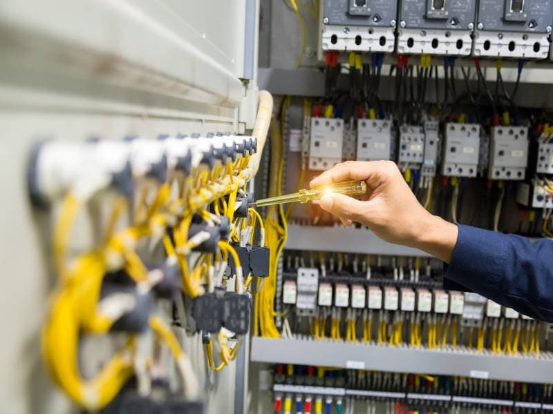
Prior to the initial commissioning of an electrical system, in accordance with DIN VDE 0100-600 (VDE 0100-600):2008-06 various measurements are to be undertaken. These include the measurement of the insulation resistance, which is measured between the active conductors and the protective earth conductor connected to earth. During this test the active conductors are allowed to be connected together electrically. The DC measuring voltage and the magnitude of the insulation resistance must comply with the requirements in Table 2. The insulation resistance is considered adequate if each circuit reaches the required value without electrical loads connected. During the measurement it is to be ensured that all switches in the circuit are closed. If it is not possible to close circuits, the electrical circuits not measured must be measured separately. Any connections between N and PE must be open.
The insulation measuring device must meet the requirements of DIN EN 61557-2 (VDE 0413-2):2008-02. The measuring voltage is a DC voltage as only Ohmic resistances are measured. The magnitude of the measuring voltage is based on the type of system or equipment to be tested and is defined in the applicable standards for safety-related tests (see Table 2 / 4). The measuring current must exceed at least 1 mA and the peak value is not allowed to exceed 15 mA.
Insulation monitoring devices (IMD) perform the task of measuring the insulation resistance in IT systems with the electrical system switched on in accordance with section 61.3.3 DIN VDE 0100-600 (VDE 0100-600):2008-06 .
| Nominal voltage of the electrical circuit (V) | DC measuring voltage (V) | Insulation resistance (MΩ) |
| SELV*,PELV* | 250 | ≥ 0,5 |
| Up to and including 500V, as well as FELV*** | 500 | ≥ 1,0 |
| Over 500V | 1000 | ≥ 1,0 |
Table 2: Insulation resistance and measuring voltage in accordance with DIN VDE 0100-600 (VDE 0100-600):2008-06
4) Insulation monitoring: in operation
During the operation of an electrical system, there are several ways to monitor the insulation resistance depending on the type of system used (IT, TN or TT system).
a) Earthed power supplies (TN/TT systems)
In the case of earthed systems, the insulation resistance is determined indirectly via the magnitude of the fault current. A classic tool for this purpose is the residual current device (RCD), which shuts down the system or the loads if a certain fault current is exceeded and in this way prevents a hazard. In areas in which a shutdown could be a problem for operations, e.g. IT systems, often residual current monitors (RCM) are used. These also operate based on the residual current principle that is the difference between the current flowing in and out is measured using a measuring current transformer and a signal provided or the system shut down at a specific fault current. Depending on the related fault current, AC, pulsed DC or AC/DC sensitive devices are used. For systems in which a large number of outgoing circuits need to be monitored, multiple channel systems are also available on the market, so-called RCMSs. RCMs must meet the requirements of the product standard DIN EN 62020 VDE 0663:2005-11. These devices are also used to monitor a “clean” TN-S system, i. e. strict separation of N and PE. In accordance with DIN VDE 0100-444 (VDE 0100-444):2010-10 section 444.4.3.2 a RCM can support the effectiveness of a TN-S system.
b) Unearthed power supplies (IT systems)
Unlike TN/TT systems, in IT systems the active conductors are insulated from earth. In these systems the insulation resistance between the active conductors and earth is continuously monitored with the aid of an insulation monitoring device (IMD). If the value measured is below a specific resistance (kΩ) an alarm is output. Here a key advantage of the IT system becomes clear. In accordance with DIN VDE 0100-410 (VDE 0100-410):2007-06 shut down is not necessary on the occurrence of a first fault such that operation can continue uninterrupted. This aspect is of crucial importance in safety-related areas, e.g. in hospitals, industrial plants or electric mobility. As the IT system supplied is in operation, the insulation monitoring device measures the total insulation resistance of the system, including all loads switched on that are electrically connected to the IT system.

The insulation monitoring device superimposes a measuring voltage Um on the system to be monitored; as per the product standard for insulation monitoring devices DIN EN 61557-8 (VDE 0413-8):2007-12 this voltage is limited to ≤ 120 V. If an insulation fault occurs, the measuring circuit closes (see Figure 2) and the resulting measuring current Im is a measure of the insulation resistance RF. This resistance is indicated by an IMD, e.g. directly as a kΩ value on a display, or via interfaces as information to higher level systems. To support service, insulation fault location systems in accordance with DIN EN 61557-9 (VDE 0413-9):2009-11 are also often used; these systems precisely identify the outgoing circuit with a fault in a very short time. Both insulation monitoring devices and also equipment for insulation fault location are therefore valuable aids for service and maintenance, as weak points are clearly identified by the early alarm; maintenance measures can be planned and initiated in good time.
Result
Insulation monitoring is not the same as insulation measurement and vice versa. Depending on the related phase of the life cycle of a system or an item of equipment, these two techniques are to be used differently. However, overall it is important that a failure or a hazard for individuals and property is avoided by a preventive action. Here insulation monitoring devices and systems for insulation fault location have been proven in particular in unearthed systems (IT systems). In earthed systems (TN/TT systems) residual current monitors are a practical aid; these monitors can also be used to optimize low-interference TN-S systems in relation to EMC requirements…
References
- Harald Sellner : Insulation resistance, testing – measuring – monitoring
- Wolfgang Hofheinz : VDE-Schriftenreihe Band 114 3. Auflage 2011
- DIN EN 61180-2 (VDE 0432-11):1995-05
- DIN EN 60204-1 VDE 0113-1:2007-06
- DIN VDE 0100-600 VDE 0100-600:2008-06
- DIN EN 62020 VDE 0663:2005-11
- DIN VDE 0100-410 (VDE 0100-410):2007-06
- DIN VDE 0100-444 (VDE 0100-444):2010-10
- DIN EN 61557-2 (VDE 0413-2):2008-02
- DIN EN 61557-8 (VDE 0413-8):2007-12
- DIN EN 61557-9 VDE 0413-9:2009-11
- DIN VDE 0105-100 (VDE 0105-100):2009-10
- DIN VDE 0100-710 (VDE 0100-710):2002-11
- DIN VDE 0100-530 (VDE 0100-530):2011-06
- DIN VDE 0100-551 (VDE 0100-551):2011-06
- DIN VDE 0701-0702 (VDE 0701-0702):2008-06
- DIN EN 62353 (VDE 0751-1):2008-08
Harun Öndül, Sales Manager Aktif Mühendislik

