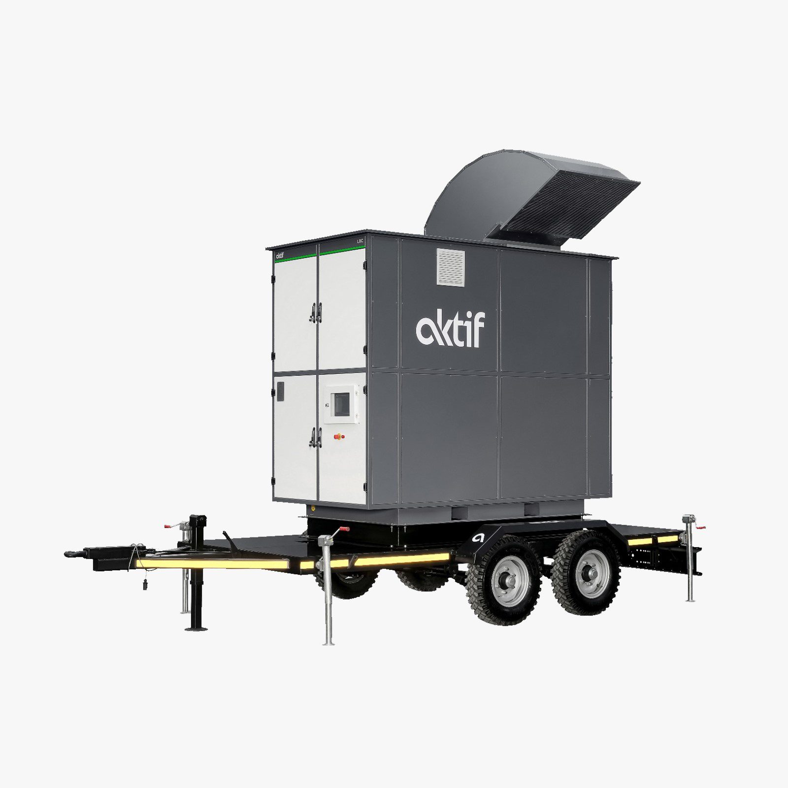
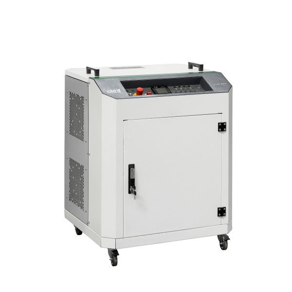
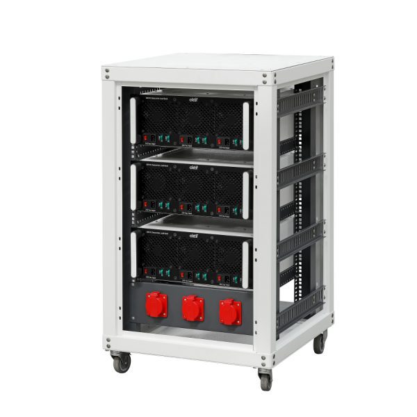
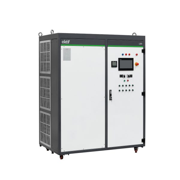
Load Banks

Load banks, which are used to test variable electrical loads, stand out with their wide range of use.

Load banks, which are used to test variable electrical loads, stand out with their wide range of use. These systems, which have a wide range of use in the industry from planned maintenance processes to generator tests, are indispensable for electrical engineering. Since the characteristics of each test are different, the load bank selection should be made carefully. This will both shorten the project time and reduce costs. It is very important to use a computerized simulation when designing load banks. Because the design of these products is based on experience and knowledge. We produce load banks with the following features for you.

Load Banks and Electrical Test System

  • Characteristics (R, L, C)
  • Electric characteristics (AC, DC, V, A, kW)
  • Stage precision
  • Control (manual, HMI-controlled or automatic)
  • Measuring methods
  • Installation (indoor or outdoor)

Usage Areas of Load Banks

Load banks are used in many industrial areas and applications. Major areas of use of load banks are listed below.

  • Testing whether the products such as power transformer, generator, alternator, UPS, regulator provide the design values and reporting the electrical values read or recorded during the test. Testing the generators, UPS or regulators after maintenance or repair.
  • No-load operation of generators is not requested. In this case, automatically providing dummy load when the load supplied by a generator falls below a certain level (ideally 30%)
  • Automatic damping of the regenerative power which is created when facilities where high-power motors are driven by regenerative drives are supplied by generators.
  • Load dispatch test at power plants.
  • Testing of alternators used by military or civil air, road or marine vehicles.
  • Controlled discharge and capacity testing of batteries.
  • Electrical and heat simulation and performance tests of data centers.
  • Invertor performance tests.

Load Banks Electrical Specifications

They can be manufactured for AC (50/60/400 Hz) or DC and AG or OG operating voltages. These series based on load characteristics;

  • Resistive (kW-cosø: 1)
  • Inductive (kVAr)
  • Resistive + Inductive (kVA-cosø: requested)

Special designs can be made for different frequency and cosø values. AC products are designed in kW, kVAr, or kVA. Load stage precisions can be 1 kW or 1 kVAr for AC or 1 A for DC standard. The resistor material for resistive loads is a stainless steel wire which has a low-temperature coefficient. This ensures that voltage and power levels are within tolerances even in case of continuous operation. Inductive loads are manufactured with aluminum or copper conductor, low losses, and iron core. Resistive load resistors provide a large cooling surface for forced cooling and are resistant to short-term overheating and cooling. The insulation level of load banks is 3 kV/1 minute for the power circuit and 2 kV/1 minutes for the control circuit. Ceramic insulation materials resistant to electricity and heat are used for insulators. Any flammable materials, including the cables, are not used in the load compartment. All serial and/or parallel power connections are made with a busbar inside the terminal board. Automatic load systems that work dummy load principle for generators are manufactured without fans and with natural cooling up to 50 kW. Single-phase or 3-phase fans are selected by analyzing the flow rate (m3 / h) and pressure (pa) values of the fan according to the power and volume of the resistors to be cooled in the load banks cooled by the fan. More information for braking resistor please click link.

Load Banks Physical Properties and Control Model

These series can be manufactured for IP20 protection levels for indoor use, IP20 for outdoor use under shelter, or IP23 for outdoor use in the open area. Load banks are manufactured portable and case-type up to 100 kW. These products up to 500 kW are manufactured with wheels. Over 500 kW this system is usually fixed on the ground. They can be installed on a trailer and transported by a vehicle on demand.

“N0” Control Model

When our customers want to control the load bank themselves, the “N0” control model is used. In this model, the load bank; includes loads, fans, sensors, and an empty control panel. The power cables of the loads, power of the fans, and the contacts of sensors are in the empty control panel.

“N1” Control Model

It is the simplest and cheapest control model. Each load phase is directly switched with a miniature circuit breaker or cam switches. A wattmeter is used for measurement.

“N2” Control Model

Loads are protected with miniature circuit breakers or compact circuit breakers and switched with contactors. Load contactors are controlled with buttons and their indicators on the control panel. The network analyzer on the control panel is used for measurement. This analyzer allows the reading of kW, kVAr, kVA, A, V, f, cosø. Optionally, an analyzer with PC communication (RS212, RS458, or USB port) is used to monitor measured values on the PC.

“N3” Control Model

Loads are protected with miniature circuit breakers or compact circuit breakers and switched with contactors. Load contactors are controlled through the interface of the touchscreen TFT LCD HMI Panel. HMI runs with a microprocessor-based electronic control board or in integration with the PLC and with a communicating network analyzer. Operators can manually switch on all loads individually or all in one go via the HMI interface and can automatically control with many control options and scenarios. Besides, kW, kVAr, kVA, A, V, f, cosø, are monitored on the HMI screen. These values can also be stored on the HMI’s memory card.

“N4” Control Model

Loads are protected with miniature circuit breakers or compact circuit breakers and switched with contactors. Load contactors are controlled through computer software. An operator can manually switch on all loads individually or all in one go via the computer software and can automatically control with many control options and scenarios. In addition, kW, kVAr, kVA, A, V, f, cosø, etc. are monitored on computer software. These values can also be stored as an excel file in the computer and memory card. Loads can be switched on only when there is no safety issue. In addition, all errors are monitored on computer software.

“N5” Control Model

Loads are protected with miniature circuit breakers or compact circuit breakers and switched with contactors. Load contactors are controlled through the interface of touchscreen “TFT LCD HMI Panel”. HMI runs with a microprocessor-based electronic control board or in integration with the PLC and with a communicating network analyzer. No-load operation of generators is not requested. In this case, Load Bank automatically provides artificial load by microprocessor-based electronic control board or PLC when the load supplied by a generator falls below a certain level (ideally 30%). Loads can be switched on only when there is no safety issue. In addition, all errors are monitored on the HMI screen.

Another point to be considered in the design of dummy loads is the safety of the person using the system and system security. They should have over-voltage protection, over-current, and temperature protection, even under-voltage protection. On the other hand, the fan blowing error can be prevented thanks to the airflow sensors. It is also important to ensure the safety of the operator who will do the load test. The design of the control panel should address these safety concerns, while the load system should be designed in such a way that the operator cannot access dangerous parts.

Frequently Asked Questions for Load Banks

What is a load banks?

Load banks are test devices that generate dummy loads for power supplies. Load banks are used extensively in production and factories, test systems. They are also a great solution for controlling backup power systems such as batteries and UPS. Which load banks are used in generator systems? A load bank for generator provides you with all the information you need about the performance of your power generating device or system under full or partial load. Such a test can be used, for example, to check the performance of generators and motors, transformers, generator controls, switchgear distribution systems and private power supply networks. Whether your device or system is in regular operation or as backup power generation, it is always important to systematically review its performance. The following four goals ensure that the load bank test is as successful as possible for generators. The best dummy load ensure the operational readiness and resilience of your generators system. It can also be used for setting, testing and maintenance as well as the technical acceptance of generators.

How many types of load banks are?

An inductive load consists of an iron core reactive element that, in conjunction with an ohmic load bank, creates a lagging power factor load. Other ratios are possible to obtain other power factor ratings. An inductive load is used to simulate a real mixed commercial load consisting of lighting, heating and transformers. A full current test is possible with a resistive inductive load bank, since the impedance provided supplies currents out of phase with voltage and enables the performance of generators, voltage regulators, switchgear and other devices to be evaluated. A capacitive load bank is similar to an inductive load bank in terms of its power rating and purpose, except that leading power factor loads are created so that reactive power from these loads is delivered to the system, thereby improving the power factor. These loads simulate certain electronic or non linear loads typical of the telecommunications.

What is a load bank used for?

They are used in many industrial areas and applications. Dummy loads are used for testing whether the products such as power transformer, generator, alternator, UPS, regulator provide the design values and reporting the electrical values read or recorded during the test. Also, load banks are used for electrical and heat simulation and performance tests of data centers. On the other hand, no-load operation of generators is not requested. In this case, automatically providing artificial load when the load supplied by a generator falls below a certain level (ideally 30%).

What is a load bank testing?

A generator should be tested with a load bank for examination and assessment. A load bank test produces artificial loads on the generator by bringing the engine to an appropriate operating temperature and pressures. A load bank test ensures that your generator will run properly when it’s needed so that you can fully depend on it during an emergency situation.

×
img