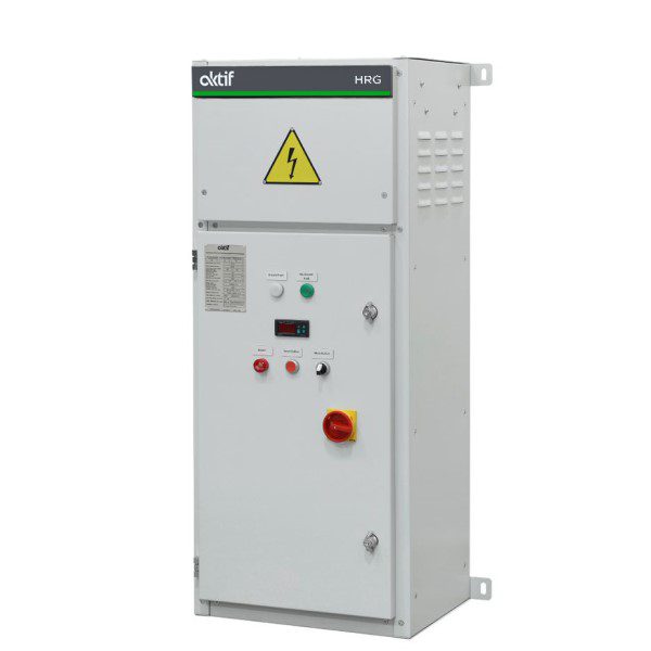
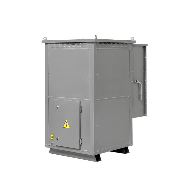
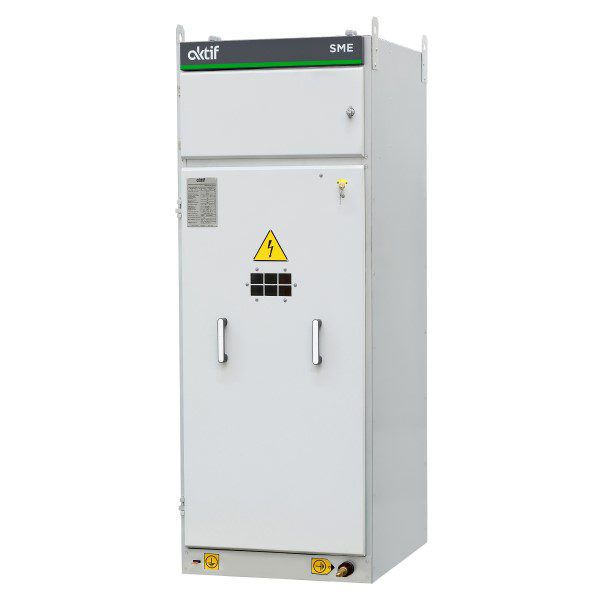
High Resistance Grounding (HRG) systems are used in hospitals, data centers, and production facilities to reduce fault currents to 5–10 A. These systems are designed to handle fault currents and offer an economical solution for 400 V–7.2 kV. However, ignoring capacitive and leakage currents may cause the system to operate in continuous fault mode.
One of the most important features of HRG systems is the possibility of detecting the location of the fault.. When a phase-ground fault occurs in the network, the HRG system automatically halves the resistance value to flow twice the nominal fault current with an average interval of 1 second (For example, 1 second 5A, 1 second 10 A). In this way, the fault current changes in such a way that the current can be easily detected even in high phase current and the currents of the outputs in the distribution panels are controlled with the help of a simple clamp meter and fault location is determined.
In contrast to other systems, Aktif’s HRG systems automatically detect the location of fault. In the control panel of the Aktif’s HRG system, in case of a malfunction in operation, it is automatically displayed from which distribution point and even which load connected to that distribution point the fault originates. If the switching equipment used at the plant have the ability to receive the external interrupt signals, the source of the failure can be deactivated.
Also, Aktif’s HRG systems automatically monitor and confirm that the system is functional. In case of a system failure, visual and audio alarms are sent to the user. Thus, it maximizes both its own an operational safety .
Advantages
- Limiting the short circuit failure current
- Detecting the location of the fault
- Monitoring the system operation
- Visual and audio failure notification
- Stable fault and pulse current with 3% resistance variation against temperature rise
- Modular and rigid enclosure design with resistor blocks mounted to the frame for safety lifting
Application Areas
- Any area where energy continuity is priority like
- Hospitals
- Data centers
- Textile factories, Cement factories
Technical Specifications
- Nominal voltage up to 7,2 kV
- Suitable for continuous current up to 10 A and impulse current up to 20 A
- Adjustable fault current, impulse time
- Smart fault detection system
- Smart auto control system to check system operation
- Current and voltage monitored on the panel
- Stainless steel resistance material suitable for extreme ambient conditions, resistant to oxidation and corrosion (AISI304, AISI310, AISI316, AISI430, CrAl, CrNi)
- Special mechanical and electrical design to withstand high temperature and extreme current values
- Design and testing in accordance with IEEE C57.32 standard and special specifications
- Spring-wound, edge-wound or grid resistor elements with a cross-section suitable for the nominal current
- Standard IP23 protection level
- Standard painted enclosure
- Lockable door with hinges
Standards
- IEEE-C57.32
- IEC 60076-25
| Type | Size | Download Link | |
| GR - Neutral Grounding Solutions | 1 MB | Download |


