
Understanding Reactive Power Compensation with Excel-Based Simulation
Contents
Introduction
Reactive power compensation is fundamental to power system management, ensuring efficient energy use and system stability. This technical article introduces an interactive Excel file designed to simulate the functioning of reactive power control relays and compensation systems. This simulation is particularly beneficial for students and professionals seeking practical experience without requiring physical equipment or laboratory setups.
Key Features of the Excel Simulation
The provided Excel file allows users to interact dynamically with essential components of a reactive power compensation system:
-
Capacitor Stages
- Six adjustable capacitor stages.
- Modify capacitor power values to explore different scenarios.
-
Motor Loads
- Five adjustable motors.
- Set various active power and power factor values.
- Activate or deactivate motors using dedicated control buttons (M1 to M5).
-
Reactive Power Control Relay Operation
- Toggle between Automatic and Manual operation modes via the [A/M] button.
Automatic Mode Operation
- Relay automatically manages capacitor stages based on the defined CosΦ target value.
- Adjust the CosΦ target value using the dedicated input field.
- Change capacitive or inductive targets using the [i/c] button; note that a target value of “1” neutralizes this function.
- Automatically activated stages appear in orange (A1 to A6).
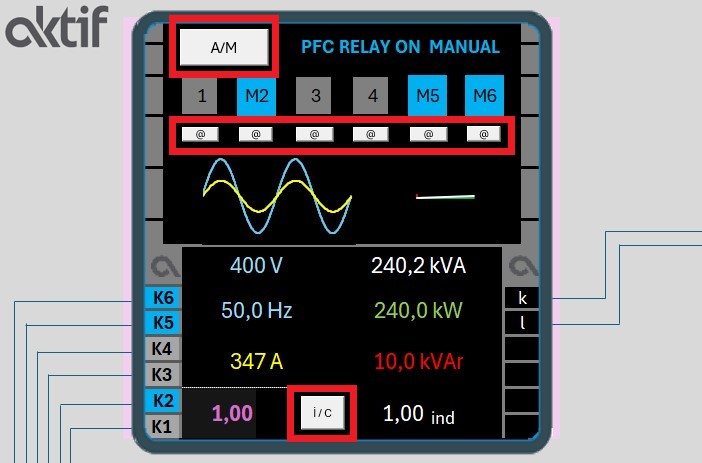
Manual Mode Operation
- Manually activate or deactivate capacitor stages using [@] buttons below each stage number.
- Manually activated stages are indicated in blue (M1 to M6).
- Deactivated stages appear grey (1 to 6).
Visualization and Analysis
The Excel simulation provides clear visual indicators to facilitate understanding:
-
Power Flow Visualization
- Reactive power flow is represented in red.
- Active power flow is represented in green.
-
Digital Display Features
- Observe phase shifts between voltage and current sine waveforms.
- Analyze power triangle variations based on CosΦ changes.
-
Transformer Load Analysis
- Automatic transformer power selection corresponding to motor load.
- Option for manual transformer power input.
- Real-time monitoring of transformer load percentage.
Practical Applications
Through interactive adjustments, users can:
- Examine impacts of varying motor loads and capacitor stage configurations.
- Analyze transformer loading variations and evaluate system efficiency improvements.
- Understand the practical implications of reactive power compensation on energy management.
Conclusion
This Excel-based simulation provides an accessible and practical tool to grasp the fundamentals of reactive power compensation systems, enabling theoretical concepts to be explored interactively and intuitively. This approach significantly benefits students and professionals aiming to deepen their understanding of reactive power management without requiring a physical laboratory setup.
Note: The Excel file might be blocked by the Windows operating system after being downloaded due to containing macro functions. To prevent this, right-click the file and get into the properties section. You will see there is a “unblock” box on the right, below the corner box mark this box and click the Apply and Ok buttons respectively.
Then reopen the file, and the file will be ready to use.

