Common Myths Regarding Power Quality and Compensation-1
Our Common Myths Regarding Compensation ve Power Quality article series consists of 4 sections. Let’s start with the first one…
We should use all levels of reactive power control relay in order to create a sensitive automatic compensation system. False. The factor determining the sensitivity in automatic compensation systems is not the multitude of level number instead power o the smallest level and a correctly adjusted step sequence. Amplitude of the maximum power required to be acquired determines number of levels. Levels are created based on certain indexes in automatic compensation systems. The purpose is to reach target power in the shortest time possible with least switching and reduce initial investment cost of the compensation system. For instance, we want to design compensation panel with 5 kVAr level sensitivity in a facility requiring 75 kVAr reactive power. If we create 15 pieces of 5 kVAr levels in order to use all levels of 15 levels reactive power control relay, we shall provide 15 x 5 = 75 kVAr. In this case, the realized sequence shall be (1:1:1:1:…:1) sequence. This system can give all powers between 0 kVAr and 75 kVAr with 5 kVAr sensitivity step.
Instead, let’s design a compensation system whose level sequence logic is (1:2:4:8). Make the level sensitivity 5 kVAr again. Our new level design shall become a system consisting of 4 levels (5kVAr + 10 kVAr + 20 kVAr + 40 kVAr). This system can provide all powers between 0 kVAr and 75 kVAr with 5 kVAr sensitivity step. When the correct sequence is selected, result can be easily achieved with 4 levels solution instead of 15 levels. Same sensitivity can be maintained by using a sequence as folds of each other instead of unnecessary multiple levels and initial investment cost can be considerably reduced by using less materials (fuse, cable, contactor, panel, etc.). Another advantage is prolonged switch equipment life due to reaching required reactive power with much less switching.
Aim of the filter in harmonic filtered compensation systems is to eliminate harmonics.
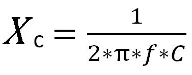
False. De-tuned reactor compensation systems used in low voltage systems do not eliminate harmonics. Moreover, these reactors are placed for protecting the capacitor by hindering harmonic currents to flow on capacitors. Capacitors are circuit elements with low impedance. Capacitor impedance is calculated with the below given formula:

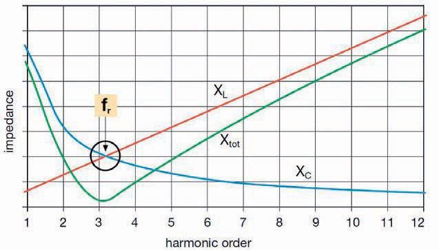
As it can be seen from this formula, increased frequency reduces the capacitor impedance. Capacitors are under stress in facilities with harmonics, namely high frequency components. Serial filter reactor is installed on the capacitor for preventing harmonic currents to flow on capacitors and damage them. Thus, as soon as this serial resonance circuit indicating high impedance in harmonic frequencies on the accord frequency withdraws harmonics, capacitors are protected.
Compensation and Power Quality | Impedance – frequency graphic of serial filter circuit

Generally active filters are used for eliminating harmonics in facilities.
Uğur YAŞA, Güç Kalitesi Müdürü – Aktif Mühendislik


