

Neutral Grounding Resistors (NGR) Explained: What They Are, How They Work, and Why They Matter?-2
What is a NGR?
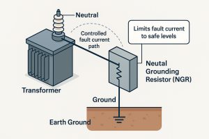
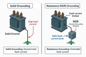
Neutral Grounding Resistors (NGRs) are critical components in electrical power systems for enhancing safety and equipment protection. An NGR connects the neutral point of a generator or transformer to ground through a resistor, limiting the fault current that flows during a line-to-ground fault. By restricting ground-fault current to a manageable level, NGRs prevent the extreme currents that would occur in a solidly grounded system (which can reach tens of thousands of amps) and avoid the transient over-voltages seen in ungrounded systems. In essence, an NGR provides a middle ground between solid grounding and no grounding – it allows enough fault current to flow for protective devices to detect and clear the fault, but keeps the current low enough to minimise damage and arc flash hazards.
Why do NGRs matter?
They are widely used in low and medium-voltage distribution networks to protect generators, transformers, and other equipment from damage while improving personnel safety. When a ground fault occurs, an NGR dissipates the fault energy as heat for the short duration of the fault, preventing excessive mechanical and thermal stress on the system. This controlled response not only safeguards equipment but also simplifies fault localization and reduces unplanned downtime. In this cornerstone article, we will explain what NGRs are and how they work, then dive into deeper topics: the terminology differences (NGR vs. NER, HRG, LRG), criteria for selecting the right NGR for a project, how to calculate and size NGRs with real-world examples, installation and operational considerations, common mistakes to avoid, maintenance and monitoring practices, and the emergence of “smart” NGR solutions. Throughout, we’ll also highlight Aktif Elektroteknik’s expertise in delivering custom-tailored NGR designs to meet each client’s specific requirements, ensuring optimal performance and safety.
NGR vs NER vs HRG vs LRG: Terminology and Grounding Methods
NGR (Neutral Grounding Resistor): A resistor connecting a system neutral to ground to limit ground-fault current (essentially the device we have been discussing).
NER (Neutral Earthing Resistor): Simply another name for an NGR – “earthing” is the British term for grounding. NER refers to the same concept and the same resistor used for neutral grounding.
HRG (High-Resistance Grounding): A grounding method where the neutral is grounded through a high-value resistor. The fault current is limited to a very low level (typically on the order of 5–10 A, just above the system’s natural leakage current). HRG systems usually do not trip on the first ground fault; instead, they raise an alarm so the system can continue operating while the fault is located and fixed (beneficial for critical continuous processes).
LRG (Low-Resistance Grounding): A grounding method where the neutral is grounded through a lower-value resistor, allowing a higher fault current (often 50–600 A range). LRG systems generally will trip the circuit for a ground fault after a short delay. This approach limits the fault current enough to reduce damage but still allows for quick fault clearing to ensure safety.
NGR Selection Criteria
Key Selection Criteria for NGRs: – System Voltage: The system’s line-to-neutral voltage determines the required insulation level and voltage rating of the NGR. It also influences the grounding approach – for example, NGRs are common in medium-voltage systems, whereas at very high voltages a solidly grounded approach is often used to avoid excessive insulation requirements.
Desired Ground Fault Current: Also known as let-through current, this is the target maximum current during a ground fault. It must be high enough for detection by protection relays but low enough to prevent equipment damage. Typically, the chosen value exceeds the system’s natural charging current but is far below the level of an unrestricted fault.
System Charging Current: The capacitive charging current of the network (from cables, transformers, etc.) provides a baseline for setting NGR current. Good practice is to choose an NGR that allows a fault current equal to or slightly above the total charging current so that even a single ground fault will register and can be addressed without causing transient over-voltages.
Continuity vs. Fault Clearance: Determine whether the facility can tolerate a ground fault without immediate shutdown. If continuity of service is critical (e.g. in mining or process industries), a high-resistance grounding (low fault current, alarm only) may be preferred. If immediate fault clearing is required (e.g. in distribution feeders), a low-resistance grounding (higher fault current, quick trip) is appropriate.
Source Type (Transformer or Generator): Generators often require lower ground-fault currents (5–10 A) to protect sensitive generator windings from damage. In contrast, transformers in distribution systems might use higher fault current limits (e.g. 50–300 A) to ensure protective relays operate quickly.
NGR Time Rating: The duration the resistor must withstand fault current (e.g. 10 s, 30 s, 60 s, or continuous). This depends on how fast the protection system will clear the fault. A system that only alarms on the first fault (HRG) may require an NGR rated for extended duration or continuous duty. –
Standards and Specifications: Industry standards (like IEEE 32) and client specifications can dictate NGR parameters such as maximum temperature rise, material, enclosure protection, and whether continuous monitoring is required. Ensure the NGR selection meets all applicable guidelines. –
Environmental Conditions: Installation location factors (indoor/outdoor, temperature, altitude, humidity, corrosive atmospheres) affect NGR design. For instance, high altitudes reduce cooling and insulation strength, possibly necessitating design adjustments, and corrosive or marine environments may require special enclosures or materials (addressed in a later section).
Sizing NGRs: Calculations & Examples
How to Calculate NGR Size: The fundamental formula for sizing an NGR is derived from Ohm’s law. For a three-phase system: NGR Resistance (Ω) = VL-N / I_fault, where VL-N is the line-to-neutral voltage of the system, and I_fault is the desired ground fault current. (Note: VL-N = VL-L / √3 for a grounded wye system.). Using this formula, engineers choose an NGR resistance that will limit the fault current to the chosen let-through value. It’s also important to ensure the resistor can absorb the fault energy: the resistor’s power rating should satisfy P = I_fault² × R, adjusted for the fault duration (time rating). Examples: – Generator example: A 11 kV (line-to-line) generator is to be high-resistance grounded at 10 A. The line-to-neutral voltage is 11,000 / √3 ≈ 6,350 V. Using R = VL-N / I_fault gives R ≈ 635 Ω. This 635 Ω NGR will limit ground-fault current to about 10 A, protecting the generator’s stator from damage. – Transformer example: A 6.6 kV distribution transformer is low-resistance grounded to allow up to 100 A ground fault. VL-N is 6,600 / √3 ≈ 3,810 V. The required resistor is R ≈ 38 Ω (3,810 V / 100 A) to limit the fault current to 100 A. If a ground fault occurs, about 100 A will flow through the resistor, which must be rated to handle roughly 100 A × 3,810 V = 381 kW (for short duration). – Low-voltage example: A 480 V AC industrial system (VL-N ≈ 277 V) uses an NGR to limit fault current to 5 A. By calculation, R ≈ 55 Ω (277 V / 5 A). This high resistance allows an alarm on a ground fault without immediate shutdown, typical for critical 480 V systems. In cases where the required NGR resistance is extremely high (for instance, on a high-voltage system with a very low allowable fault current), it may be impractical to build a physically large resistor. In such scenarios, a Neutral Grounding Transformer (NGT) can be employed – using a transformer to create a neutral at a lower voltage and placing a smaller resistor on that side,which reflects a high resistance to the primary side.
Installation Considerations
– Heat Dissipation: NGRs convert fault energy to heat, so they can become very hot during a fault (often hundreds of °C temperature rise). They should be installed in a location with adequate ventilation and away from flammable materials. Typically, NGR enclosures have vented panels or louvers; ensure these are not blocked. Personnel should be warned of hot surfaces (labels or signs like “HOT” and “High Voltage” on the enclosure). – Location and Mounting: Mount the NGR as close as practical to the neutral connection (e.g., near the transformer or generator) to minimize wiring length. Outdoor installation is common for medium-voltage NGRs – the enclosure should be weatherproof (sufficient IP rating) and elevated if flooding is a concern. Ensure the enclosure is solidly grounded and accessible for inspection. Provide adequate clearance around the unit for cooling and maintenance access.
Neutral Connection and Cable Routing: Use appropriately rated cable for the neutral lead connecting the system neutral to the NGR (it must withstand full line-to-neutral voltage). This conductor should be as short and straight as possible to reduce inductance and voltage drop. Route the NGR connection away from sensitive control cables to minimise electromagnetic interference during fault events. The ground lead from the NGR to the earth grid should be low-impedance (typically a short, robust copper conductor) and securely bolted to the ground bar.
Accessibility and Safety: Install the NGR in a way that maintenance personnel can easily access it for periodic inspection or replacement. There should be sufficient space to open panels or remove resistor banks safely. Barrier or fencing may be necessary to prevent accidental contact with the NGR, especially if it’s in an open area. Before energising, verify that all connections (neutral and ground) are tight, and that the NGR is properly integrated into the ground fault protection scheme (e.g., any neutral ground CT is correctly positioned).
Common Mistakes
Common Mistakes and How to Avoid Them: – Selecting an Improper Resistance Value:
A frequent mistake is choosing an NGR with too high a resistance (resulting in a very low fault current). If the allowed ground-fault current is set below the system’s natural charging current, a single line-to-ground fault may go undetected, and dangerous transient over-voltages can occur. Conversely, using too low a resistance defeats the purpose of limiting fault current and can subject equipment to higher-than-intended fault stress.
Avoidance: Calculate the system’s charging current and select the NGR let-through current equal to or above that value, but still low enough to protect equipment.
Wrong Time Rating or Undersized Resistor: Installing an NGR rated for too short a duration (or insufficient wattage) can lead to resistor failure. For example, using a 10-second rated NGR in a system where ground faults might persist for longer will overheat the resistor.
Avoidance: Align the NGR time rating with the protection scheme – if the relay might not clear the fault quickly (or only alarms on first fault), use a longer time or a continuously rated NGR. Ensure the resistor’s power rating comfortably exceeds I²R for the fault duration.
No Monitoring of NGR Continuity: If an NGR burns open or a connection is loose, the system becomes ungrounded without anyone’s knowledge. This negates the benefits of the NGR and can introduce over-voltage risks.
Avoidance: Use a neutral-grounding resistor monitoring device or an alarm on zero ground current to detect an open NGR. Periodically test or measure the NGR’s resistance during maintenance. –
Improper Ground Relay Settings: In some cases, ground-fault protection is set incorrectly (e.g., too high or too low) for an NGR-equipped system. If too high, it may not detect the limited fault current; if too low, it may nuisance-trip on charging current or harmonics.
Avoidance: Coordinate ground relay pickup and delay settings with the chosen NGR fault current. For instance, set the relay to just above the expected charging current (perhaps ~1.5 times the charging current) and with a short time delay to ride through the transient inrush.
Multiple Grounding Points: Another mistake is leaving multiple neutrals grounded (e.g., two transformers both solidly grounded while an NGR is also connected). This can bypass the NGR and make it ineffective.
Avoidance: Only one grounding method should be used on a given system section. Ensure that when an NGR is in service, no parallel neutral-ground connections exist (disconnect any solid grounds or additional NGRs not meant to operate simultaneously).
Maintenance & Monitoring
Regular Inspections: Implement a routine (e.g., every 6-12 months) to visually inspect the NGR and its enclosure. Look for signs of overheating (discolored or charred components), corrosion on connections or resistor elements, moisture ingress, or accumulated dust and debris that could impede cooling. Ensure all electrical connections (neutral and ground) are tight and free of corrosion. –
Resistance and Continuity Checks: During scheduled outages, isolate the NGR and measure its resistance with an ohmmeter to verify it is within the expected tolerance. An open-circuited or significantly off-value resistor should be replaced immediately. Also verify any auxiliary devices (like cooling fans or space heaters in the NGR enclosure) are functional.
Ground Fault Tests: Periodically test the ground fault protection scheme. This can be done by using test equipment or built-in test functions to simulate a ground fault and ensure that the relays and alarms operate as intended. If the NGR system includes a pulsing feature for fault location (common in HRG systems), test that feature as well.
Monitoring Systems: Consider using a continuous NGR monitoring device (many modern systems have them) that alerts if the NGR goes open or if abnormal conditions arise. These devices can measure NGR resistance, temperature, and leakage current continuously. Integration with a digital SCADA or alarm system means maintenance personnel are notified promptly of any issues (this is part of “smart NGR” solutions).
Cleaning and Environment Control: Keep the NGR enclosure clean. Remove dust buildup on resistor banks or vents during maintenance—this ensures proper cooling. In humid environments, check that anti-condensation heaters (if present) are working to prevent moisture that could corrode the resistor. In corrosive or coastal areas, inspect protective coatings and consider a shorter inspection interval due to harsher conditions.
Record-Keeping: Maintain a log of NGR maintenance. including inspection dates, measured resistance values, and any ground fault events or alarms. Tracking these over time can help predict when the NGR might need replacement and can be useful in forensic analysis if a problem occurs.
Smart NGRs & Digitalisation
“Smart” NGRs and Industry 4.0: The latest generation of NGR systems are equipped with digital monitoring and connectivity features. These smart NGRs integrate sensors (for temperature, current, continuity) and communication modules to provide real-time status updates. For example, a smart NGR can automatically send an alert to a control center if a ground fault occurs or if the resistor is overheating or has become open-circuited. This enables remote monitoring of the health of the grounding system. In an Industry 4.0 context, smart NGRs can feed data into a facility’s SCADA or IoT platform. Maintenance teams can analyze trends such as how often ground faults happen or if the resistor’s resistance is drifting over time, enabling predictive maintenance rather than reactive fixes. Remote diagnostics allow experts to troubleshoot grounding issues without being physically at the site, which can reduce downtime. Some advanced NGR setups also include features like pulsing ground fault detection, where the NGR system briefly modulates the fault current to help maintenance personnel pinpoint the fault location in the field using handheld detectors. All these digital capabilities enhance the safety and reliability of the system.
Aktif Elektroteknik keeps pace with these innovations by offering NGR solutions that are “smart” and ready for integration into modern digital infrastructures. Whether it’s simple remote alarm indication or full IoT-enabled NGR units, the goal is to ensure the neutral grounding system can be monitored and managed as part of the overall intelligent power system.
Environmental Considerations
Environmental Factors in NGR Design: Different environmental conditions require adjustments in NGR design and materials: – Corrosive or Chemical Environments: In facilities with corrosive gases or chemicals (e.g., petrochemical plants, wastewater treatment, battery rooms), standard steel parts of an NGR may rust or deteriorate quickly. To counter this, NGRs can be built with stainless steel or specially coated resistor elements and enclosures. Regular maintenance (more frequent inspections and cleaning) is advised in such environments. Additionally, ensure a high ingress protection (IP) rating to prevent corrosive particles or vapors from entering the enclosure. – Marine and Coastal Areas: Near the sea, equipment faces salt spray, high humidity, and potentially strong winds. NGR enclosures should be made of 316 stainless steel or similarly marine-grade materials to resist salt corrosion. All hardware (bolts, terminals) should be corrosion-resistant. Often, heaters are installed inside the NGR panel to avoid condensation from the humid air. In offshore platforms or shipboard use, NGR assemblies might also need to meet marine certifications and be designed to withstand vibrations and shocks. Space constraints on ships may necessitate custom compact designs, a strength of Aktif Elektroteknik’s project-specific approach. – High Altitude: At high elevations (typically above 1500 m), thinner air means reduced cooling ability and lower dielectric strength. NGRs at altitude may run hotter for a given current and voltage, and electrical clearances inside the enclosure may need to be increased to avoid flashover. Manufacturers should be informed of the installation altitude so they can derate the resistor or provide larger spacing as needed. As a guideline, above certain altitudes, an NGR might require a higher power rating or a fan cooling system to dissipate heat effectively. –
Temperature Extremes: Although not explicitly mentioned, temperature is another environmental factor. In very hot climates, an NGR may need derating or ventilation/fans; in very cold climates, the enclosure may require heaters to prevent condensation and brittle fracture of components. All these environmental considerations are part of tailoring the NGR design to ensure reliable operation in any conditions.
Related Reading: Reasons to Use A Neutral Grounding Resistor?
Conclusion
Conclusion: Neutral Grounding Resistors are indispensable for creating safer and more reliable power systems. By carefully selecting and sizing an NGR, engineers strike a balance between fault detection and equipment protection. From understanding terminology and design calculations to considering installation and maintenance, every aspect plays a role in the NGR’s effectiveness. Modern, digitally monitored NGRs further enhance system insight and safety. Aktif Elektroteknik prides itself on delivering high-performance NGR solutions tailored to each project’s unique requirements. With expertise in custom resistor sizing, robust design for any environment, and integration of smart features, Aktif ensures that your neutral grounding solution will provide optimal protection and adaptability for years to come.

