

Pwm at Dc – Ac Inverters
Ali Gökhan Yıldırım
Product & System Sales
Aktif Mühendislik
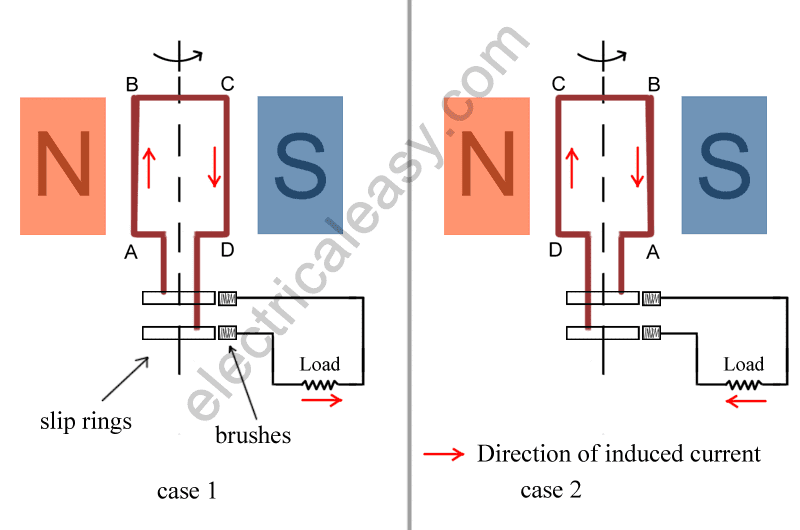
Traditionally, electrical energy is generated by alternating sinusoidal voltage and current through rotating machines. In recent years, with improvements in power electronics, semiconductor devices have begun to be used more and more to convert direct current into traditional alternating current.
I. INTRODUCTION
The inverter is a system that converts dc current to ac current. Inverters are used in many areas like photovoltaic systems, ac motor control, uninterruptible power supplies, induction heating, electronic ballasts.
DC-ac converters are forced commutations. It is usually carried out with fully controlled elements and is controlled by the PWM method. Harmonics are generated at an independent ac output voltage which can control voltage and frequency. Significant fluctuations may also occur in the DC input source current. These harmful effects can be prevented by various methods and applications.

II. CONTROL METHOD
The operating principle of the inverters is based on the dc input voltage being positive load in the first half period and negative load in the second half period. The summation of these two half periods determines the operating period or frequency of the cycle. Because this work is done with semiconductor elements, the static inverter term is used extensively.
It is quite easy to generate a square wave by switching the source positive and negative. Depending on the circuit, square wave can be converted into sinusoidal wave signal with pwm and filtering methods. The waveform can be refined until the ideal sinus signal is reached.
In practice there is no definite view that defines a pure sinus wave. Various manufacturers offer products with different properties. The output voltages, which are generally less than 3% of the total harmonic distortion of the voltage waveform, can be considered as a true sine wave that can be used for practical purposes. Pure sine wave inverters are more complex and more costly. It is best to select the inverter to match the application to be used.

III. PULSE WIDTH MODULATION
Generally positive and negative signals generated for each phase are applied to the relevant positive and negative elements. However, the signal ac is generated independently from the network and optionally. The control signals are obtained by comparing the alternating control voltages in the form of square wave or sinusoidal wave at the desired frequency and phase number with an alternative carrier voltage at the higher frequencies in the triangular wave form. This control method is generally called ac pulse width modulation (PWM).
The inverter uses the pwm method to switch on and off the DC voltage within a certain period of time. This is the variation of the duration of each pulse. Thus, the electrical effect at the output resembles a sinus wave.

IV. SWITCHING EQUIPMENTS
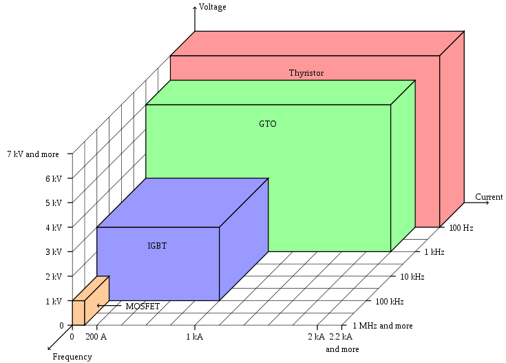
The switching equipment used in the Pwm Method varies. In the types with thyristor, it is necessary to forcibly cut the thyristors which are triggered and enter the transmission. For this reason, the inverters are known as forced commutated circuit types. In principle, it can be said that inverters use SCR at high power low frequency, bjt at medium power and medium frequency and MOSFET power element types at low power and high frequency. IGBT is the most commonly used power element in medium and slightly higher power and frequencies in forced commutated circuits in recent years. MOSFET is preferred at up to 10kW power levels and IGBT is preferred for more than 10kW power levels.
V. H – BRIDGE CIRCUIT
An inverter consists of a circuit known as h bridge regulation. The following circuit shows the application of a single-phase full bridge circuit using IGBT.
The operation of the H bridge circuit is quite simple. The IGBT acts as a switch. When a signal is applied to the gate of the IGBT, the switch goes to the ON position, and then switches back to the OFF position when the signal disappears. This signal is sent to Q1 and Q4 and applied to the positive dc source to load. By applying a signal to Q2 and Q3, the dc source is applied to the load in the negative direction. The control circuitry is used to generate the necessary PWM waveforms by generating the necessary gate signals.
To prevent a short circuit, it is necessary to turn off the next IGBT set before turning on a set IGBT while turning polarity. All IGBTs must be switched off during the transition. The diodes provide a path for inductive current to limit the potential voltage generated during the transition. The capacitor provides regulation to compensate for a change in the dc source.

VI. INVERTER BLOCK DIAGRAM
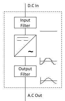
THE BLOCK DIAGRAM SHOWS THE MAIN COMPONENTS OF A DC AC INVERTER.
The input filter removes dc fluctuations or frequency distortions in the source. It provides a clean voltage to the inverter circuit.
It functions as the main power circuit of the inverter system. This circuit converts the dc voltage to the required multilevel PWM waveform.
The output filter contributes to the generation of a sinusoidal signal by damping the high frequency components present in the PWM waveform.
If you are knowledgeable about Fourier analysis; you know that the periodic waveform consists of the main fundamental frequency component and higher order but smaller harmonic components. These are high level harmonic components that the output filter removes.
VII. CONCLUSION
Inverters are complex devices, but they can convert DC to AC for general power supply usage. With the advances in power electronics and microprocessors, the usage of inverters is increasing in many areas. In an inverter, DC power input can be a battery, solar panel, fuel cell, or any other DC source. However, in many industrial facility, inverters are fed with rectifiers and in this configuration they are converted ac to dc, the dc line is filtered and converted into the desired ac frequency to make it usable for the requirement. Sometimes this can be a solar power plant that is powering the network, sometimes it is a motor drive that is used for production purposes.
REFERENCES
[2] Güç Elektroniği Prof. Dr. Hacı Bodur BİRSEN YAYINEVİ
[3] http://myelectrical.com/notes/entryid/250/how-d-c-to-a-c-inverters-work
[4] DC/AC Pure Sine Wave Inverter Jim Doucet Dan Eggleston Jeremy Shaw
[5] https://www.pantechsolutions.net/powerelectronics-tutorials/introduction-of-igbt-based-single-phase-pwm-inverter
[6] ELECTRICAL SYSTEM (MOTOR CONTROL) OF A SERIES HEV National University of Sciences and Technology (NUST), Islamabad, Pakistan
[7] http://www.electricaleasy.com/2014/02/AC-generator-alternator-construction-working.html

