
Wireless Power Transmission Basics And Application Areas
Cemil Aktaş
R&D Engineer
Aktif Mühendislik
Starting with Tesla, there has not been serious work for many years after the death of Tesla on the topic of wireless electricity transfer, which gives a different perspective to the overdue electricity transfer over 100 years. However, due to the increasing needs, especially in the last 15 years, serious work on the subject and the getting started to results and application areas of wireless electricity is discussed in this article.
1. INTRODUCTION
Electricity has inevitably become a part of human life, and even in the simplest processes it becomes a source of dependence. However, like most sources, electricity is limited source. Distribution of electricity is costly and the chaos of the cables are another source of trouble. In addition, the adventure of wireless power transmission which started with Tesla, has become increasingly important with the direction of technology as a multi-disciplinary field, and has become a common working area of different disciplines. Moreover, it plays an important role in the passage of a number of proposals that have been shown as solutions to possible problems in the future.
2. BASIC OF WIRELESS POWER TRANSMISSION
As well as different wireless power transmission methods, these methods can be grouped as follows:
Close distance:
- Inductive Coupling
- Resonant Inductive Coupling
- Air Ionization
Long Distance:
- Microwave Power Transmission
- Laser Power Transmission
The accelerating method in recent years is the Resonant Inductive Coupling and brief information on methods other than this will be given.
2.1. Inductive Coupling
Inductive coupling is used when the receiver and transmitter are very close together. The most common usage areas are transformers, electric toothbrush charging stations and similar charging stations.
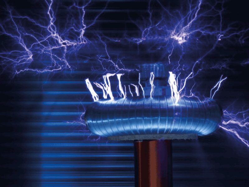
2.2. Air Ionization
Conduction is by air. It is a difficult technique and needs very high electromagnetic fields. The best known application area is some lighting materials.
2.3. Microwave Power Transmission
Makes it possible to transfer power to long distances with microwave. In the transmitter section, the electrical energy is converted to microwave energy. In the receiver part, this energy is taken with the help of the rectenna and converted to the electrical energy again.

In this area, one of the most serious works was made by Canadian Communications Research Center in 1980’s and the project name was SHARP (Stationary High Altitude Relay Platform). In this project, an aircraft without any built-in energy source could only be flown for over a month in a 2 km circle at a height of 21 km with microwave energy. Moreover, it is envisaged that the solar power plant will be installed on the moon and the energy obtained will be transferred to the world by MPT method as one of the future projects.
2.4. Laser Power Transmission
They are directional, but weak as they move in the atmosphere. Photovoltaic cells are sufficient for the receiver.
2.5. Resonant Inductive Coupling
It is a method that has been particularly studied and has achieved successful results in the recent past. It is based on magnetic resonance and it is possible to transfer to far distances compared to the Inductive Coupling method.
Resonance is the tendency of a system to oscillate at a given frequency at maximum wave width. This frequency is called the resonance frequency. Objects with the same resonance frequency tend to transfer energy with high efficiency. The basis of wireless power transmission is also based on magnetic resonance.
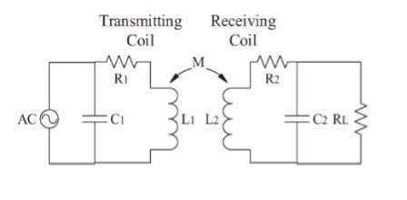
As shown in Figure 1, high frequency switching (oscillation) provides the formation of a variable current magnetic field on the transmitter coil. Current is generated on the bobbin of the receiving circuit in the magnetic field having the same resonance frequency as that of this circuit so that power transmission is ensured. The important thing here is that the resonance frequencies of the coil and capacitor pairs in the receiver and transmitter circuits are the same. Otherwise, the surrounding magnetic energy cannot be emitted by the receiving circuit.

Impedances of the coil and capacitor in the LC circuit shown in Figure 2, also called tank circuit:


It is the frequency resonance frequency that will take infinite the value of the equivalent impedance given in the formula, and the circuit generates this frequency signal. The resonance frequency can be found by this formula.
![]()
It consists of 4 basic steps through resonance on capacitor and coil:

1. First, as the charged capacitor discharges through the coil, the current flowing through the coil causes the magnetic field on the coil. This operation continues until the capacitor is completely discharged.
2. When the capacity is fully discharged, the magnetic field around the coil begins to break down and the current flowing in the reverse direction through the coil until the collapse is completely finished charges the capacitor in reverse polarity to the first stage.
3. As the capacitor is discharged through the coil, the current flowing through the coil provides a magnetic field again around the coil. This operation continues until the capacitor is completely discharged.
4. The magnetic field around the coil begins to collapse and the current flowing over the coil until the collapse is completely exhausted recharges the capacitor to the same polarity as the first stage.
But this event cannot continue cyclically. Because, the coil, capacitor and the conductive path which is used for connection have built-in resistance and causes to the loss. In addition, the oscillation is gradually extinguished because magnetic field generation and magnetic field generation are not 100% efficient. In Oscillation, it is prevented extinction with positive feedback.
APPLICATION AREA
Recent studies on the Resonant Inductive Coupling method have started to commercialize. The greatest example of this is Witricity. A new technology for wireless power transmission was invented and patented in 2006 by a team of physicists from the Massachusetts Institute of Technology (MIT), led by Professor Marin Soljačić. Witricity was founded in 2007 by this team to commercialize this new technology. The crew succeeded in burning a 60W light bulb at a high efficiency of 2 meters away. For now, a lot of wireless charging devices are developed for instruments like mobile phone, laptop, remote control devices, also electric motor featured vehicles in automotive industry. Work is continuing in the medical field.
Many of the products that are being commercialized and developed on wireless power transmission technology come into life in the following areas. Some of them seem to enter our life in the near future. These areas are:
- Consumer electronics:
Products like wireless charging pads and wireless charging tables have begun to take place in market.
- Automotive:
A wireless charger for electric vehicles has been developed and commercialized. In some production vehicles, in-car wireless charging pads have started to be offered as an option.
- Medical:
There are studies about the charging of medical products such as pacemaker while inside the body.
- Industry:
Work is being carried out on the electrical supply of equipment found in dirty and difficult to connect environments.
- Energy:
The solar power plant is installed on the moon and the generated energy is sent to the earth using wireless power transmission technology as a future project.
In addition, companies like Texas Instruments, Linear Technology have customized chips for wireless charging circuits.
3. RESULT
The wireless power transmission technology that Tesla inherited to the world more than 100 years ago has recently been started to rediscover. It is obvious that this technology can be used effectively in the near future, since it is thought that everything can be changed in in the world of mobilization.
REFERANSLAR
[2] S. Sheik Mohammed, K. Ramasamy, T. Shanmuganantham “Wireless Power Transmission – A Next Generation Power Transmission System” 2010
[3] https://powerbyproxi.com/wireless-power/
[4] http://4hv.org/e107_plugins/forum/forum_viewtopic.php?74096.0
[5] https://www.slideshare.net/soumyaprateekmuni/wireless-power-transmissionfuture
[6] http://megep.meb.gov.tr/mte_program_modul/moduller_pdf/Osilatörler%20Ve%20Filtre%20Devreleri.pdf
[7] https://www.allaboutcircuits.com/textbook/alternating-current/chpt-6/parallel-tank-circuit-resonance/
[8] http://adsabs.harvard.edu/abs/1985gtc..conf..960S

